 PoBot
PoBot
 12/04/14
First steps
After an overnight charge, the beast is sated (burp) and we can switch on for good now.
It takes its time and after several minutes keeps displaying the number "3" on its mouth and doing nothing else. Strange... They could have displayed "42" instead :) Five minutes later the situation is unchanged, so I slide the on/off switch to OFF, but without very much hope, being prepared to end up disconnecting the battery (Please Dave, don’t do this...)
To my great surprise, the shutdown process starts and completes fine. Back to ON, and the start sequence executes again, but this time it goes to the end, displaying the robot IP address on the mouth.
Just forget the web based interface for the moment, and connect to the RasPi via ssh. It works, but it is a bit sluggish. It seems that there are a lot of people struggling for the CPU here :/
We are now ready for the ROS tutorials available on the the Web site. But before doing this, a quick tour inside the beast would please me a lot. After all, we are reviewing a product. Let’s go to send the Aisoy to sleep by sliding the switch to OFF and prepare the screwdrivers.
Shutdown is complete now, but how can the battery be disconnected ? There is no connector accessible in the battery case. This case is by the way fay to large for the pack, and this one tends to dance a lot in it when moving the Aisoy. A small piece of foam would have been welcomed to gently block the pack in the case. Aisoy’s designers have overlooked some details while doing their job ;)
Inside Aisoy
I have retrieved the DIY kit assembly instructions. If I read them as if it were a Manga or the Coran (i.e. starting from the end), maybe I should be able to disassemble it :)
The touch sensors
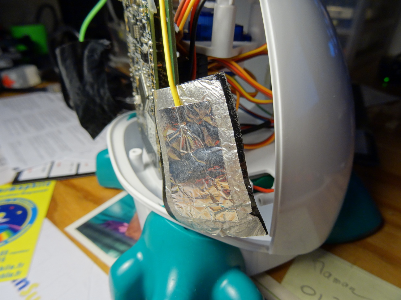
Let’s go. I found the connector of the battery by gently pulling the wire and could disconnect it. The base srews are removed, and same for the 4 ones of the back. The taps for the bottom ones pits were not that easyto remove, and I decided that will not be reinstalled, since there are a lot of chances that it will not be the last occasion for Aisoy to be opened again. I gently pull the back plate off, and it was a good idea since the touch sensors are just metallic adhesive foils stuck on the inside face of the back and connected by wires going directly in the guts of the electronic boards and not equipped with easily reachable connectors. In addition, the adhesive is not that much resistant and the wire is only pinched between the foils. One of the wires went out despite all the care I could take. This will have to be fixed and improved.
FIXME Add a connector on the wires (done on 20/04/14)
Camera cable connector
Continuing our inspection.
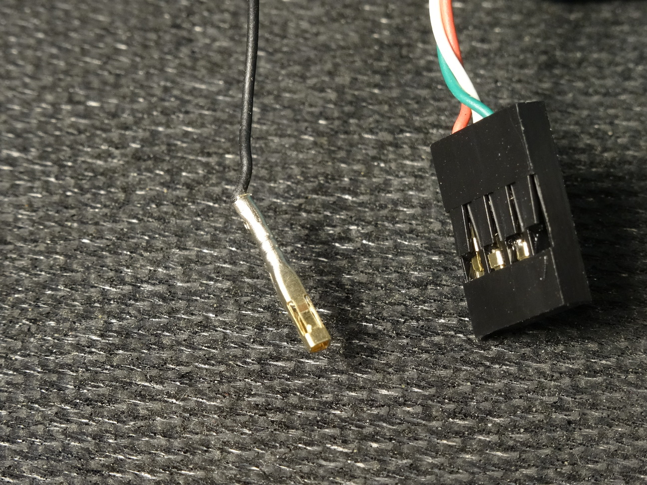
Heck, what is this flying black wire around, not connected anywhere ? Seems to be a ground. But why is it unconnected like this ? Hell, because it does not fit in its connector :( And why does not it fit ? Well... because instead of crimping it in the contact, they just soldered it :(
And it is the same for the 5V red wire. For sure, we will have some problem when trying to use the camera later :/
FIXME Refactor the connector, but I’ve none in stock of the right kind. I’ll have to improvise as usual. (done on 20/04/14)
The servo cable
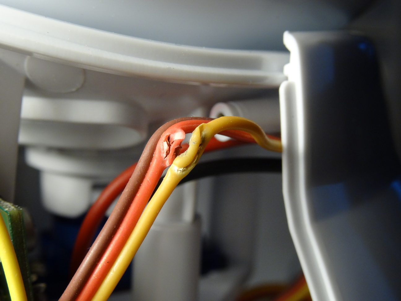
Let’s go ahead and explore. Yup, this servo cable is in a really bad shape :(
Gosh, they didn’t pay very much attention when closing and screwing the back plate, and the wire has been pinched between the cover parts and chewed by the screw. Result : the power and signal wires and naked, and for sure have been in contact via the screw. Let’s hope the driver interface or the servo itself have not been damaged.
FIXME Repair the servo cable (done on 20/04/14)
The wandering LED

Lets’ have a closer look to the electronic boards now. Two boards connected by several rows of headers... unfortunately soldered :( Few chances to be able to take advantage of spare connections available for adding extra sensors, as documented in the assembly instructions.
Another detail I really dislike : the boards are fixed in place by spots of hot melt glue :( By chance it was not that difficult to remove them. Please Aisoy, don’t forget this is a kit targeted for people who will (for a good share of them) experiment with mods and enhancements. Do not use the same bad practices as all these low end Chinese makers assembling poor quality products supposed to be trashed as soon as they fail.
Ok, the boards can be gently removed from their supports, but while doing this the green power indicator LED just falls like tree leaves in autumn. I was thinking that components were supposed to be soldered to their board ;)
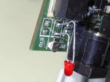
Ahem, the LEDS are not really soldered as through holes components, by glued in surface by the ends of their legs. Maybe there has been an error with the holes diameter, and the lags do not fit in them. Something is by the way blocking one of the holes, and I didn’t succeed in removing it.
Only possible repair : tin glueing the ends of the legs, but being a bit more generous with tin.
In addition, having these LEDS kept in place just by there bent legs is a bit hazardous, since it is quite easy for these legs to come in contact with each other while manipulating the boards. Using right angle housings would have been preferable (or better, SMD LEDS and light guides attached to the case instead).
Miscellaneous
Apart from that, there are also several bad insulated wires here and there. First of them are the power supply directly coming from the battery, which are directly soldered on the board instead of using a locked 0.1" polarized connector such as Molex KK series or alike. Pieces of hot shrink tube have been put on the wires, but they do not entirely cover the naked copper and slide along the wires (they seem to be of wrong diameter).
Okay, so this first tour is a bit worrying. Some aspects of the product design and assembly would have deserved more attention.


